Wednesday 2 November 2016

PMMA(poly methyl metha crylate)


POLYMETHYL METHACRYLATE  (PMMA)

INTRODUCTION
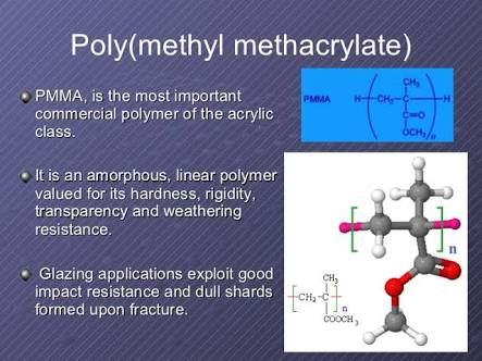
Polymethyl methacrylate (PMMA) has many excellent performances such as lightweight, high temperature resistance, high light transmittance, and superior mechanical properties. Thus, the structures made of PMMA are widely used in aviation field.
The mechanical properties of PMMA have attracted considerable attentions since several planes crashed were caused by the cracks in the hatch. The researches in the fatigue and fracture properties of polymer materials started from the 1960s for the strict requirements of strength and reliability. Berry (1961) confirmed that Griffith strength theory could be used to analyze the brittle fracture of PMMA. Recently, this theory and experiments have become the important principles to analyze the brittle fracture of polymer material. Mukherjee and Burns (1971) proposed that the fatigue behaviors of PMMA were determined by three parameters: stress intensity factor amplitude, average stress intensity factor and frequency. Woo and Chow (1984) unified fatigue crack propagation formula of metal aluminum and nonmetal PMMA. They proposed that strain energy release rate amplitude should be used to analyze the crack propagation but not stress intensity factor amplitude. Cheng (1990a, 1990b) studied the influence of temperature and loading rate to tensile strength and fracture toughness of PMMA. Kim (1993, 1994) proposed that fatigue crack growth rate of most polymers increased with the temperature increasing and decreased with the loading frequency increasing. Ramsteiner and Armbrust (2001) solved some fatigue experimental questions of polymers such as the measurement of crack propagation, the influence of the specimen shape and the applied frequency, the measurement with constant or increasing stress intensity amplitude, and the propagating crack as a signal for transitions in internal deformation mechanisms. Yao (2002, 2003, 2004) investigated dynamic fracture behavior of thin PMMA plates with three- and four-parallel edge cracks by means of the method of caustics in combination with a high-speed Schardin camera; dynamic fracture behavior of the thin PMMA sheet with two overlapping offset-parallel cracks under tensile loading using the optical method of caustics in combination with a Cranz-Schardin high-speed camera; and the fracture characterization of a V-notch tip in PMMA material by means of an optical caustics method, respectively. Sahraoui and El Mahi (2009) measured the dynamic fracture toughness of notched PMMA at high impact velocities, where the classical method was limited by the inertial effects. The direct measurements of the specimen deflection were successfully used for the toughness evaluation.Sauer and Hsiao have started to investigate the craze phenomenon of polymer early in 1949. Simultaneously, Kies and his co-workers got some inspiration for the top of PMMA hatch have the better craze resistance, and researched biaxial and multiaxial tension directional PMMA. Directional PMMA is manufactured in the following way: PMMA plate is pulled under directional stresses according to a pre-selected temperature curve including the heating, keeping and cooling. Compared with normal PMMA, directional PMMA has more excellent mechanical properties such as higher pull strength and elasticity module. Some important elements of airplanes are made of directional PMMA plates such as hatches.
The previous studies have made a tremendous contribution to the failure research of PMMA. However, most of the previous researches are based on the isotropic mechanical model. On account of the special processing of directional PMMA, it is difficult to reflect the mechanical properties of directional PMMA with the isotropic mechanical model. The purpose of this paper is to establish an anisotropic mechanical model by isodyne method and measure all the mechanical parameters by the digital image correlation method for the aeronautical directional PMMA. Furthermore, we also utilized the FEM numerical simulation and experimental methods to study the fracture mechanics properties of directional PMMA in two different directions: One is along the direction of directional tension and the other is along the vertical direction of directional tension.
http://www.scielo.br/img/revistas/lajss/v11n10/05t01.jpg
FRACTURE MECHANICAL PROPERTIES
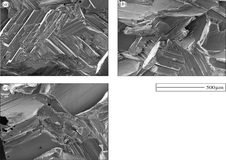
Because of the anisotropic mechanical behaviors in directional PMMA, the fracture mechanical properties of crack propagation along different directions are different. According to the anisotropic mechanical model and mechanical parameters, finite element method (Chan et al., 1970) is used to calculate stress field and strain field around the tip of crack along different directions. One is along the direction of directional tension; the other is along the vertical direction of directional tension. Three point bending specimen is modeled and the size and load of specimen1 and specimen2 The length of the model is 40cm, the width is 10cm, and the length of crack is 5 cm. The area of the crack tip is singularity, so around this area singularity element which is a kind of triangular element of six nodes is used.Directional PMMA is a kind of polymer material. It is composed of molecular chains and brittle material, so the damage of directional PMMA is relative with the deformation. Asthe analysis to the strain around the tip of crack shows that the values of shear stress are small compared with normal stress, but the values of shear strain and normal strain are in the same level, so shear stress could not be neglected. In the same stress state, the strain values around the tip of the specimen2 are larger than that of the specimen1, so the crack along the vertical direction of directional tension extends more easily
http://www.scielo.br/img/revistas/lajss/v11n10/05t02.jpg


Fracture of Polymers
  • Fracture strengths of polymers are low compared tometals and ceramics.
  • Brittle fracture occurs in thermosetting polymers.Fracture is initiated at stress concentrators (scratches notches, etc). Covalent bonds are severed during fracture
  • In thermoplastic polymers, both ductile and brittle fracture are possible Brittle fracture is favored atlower temperatures, higher strain rates, and at stressconcentrators
  • Brittle to ductile transition often occurs with increasing temperature
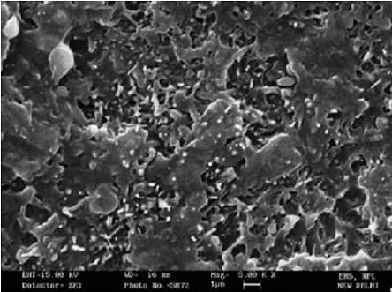
Microstructure Of  PMMA
APPLICATIONS OF PMMA:
 
CONCLUSIONS:
As the anisotropic mechanical properties in the directional PMMA, the fracture mechanical properties of crack propagation along different directions are different which are analyzed by experimental methods. The stain values of the crack tip along the different directions of crack propagation  which indicates that the crack along the vertical direction of directional tension extends more easily than that along the direction of directional tension. Fracture toughness value measured by experiment along the direction of directional tension is larger than that along the vertical direction of directional tension. So the crack along the vertical direction of directional tension extends more easily.

zinc

MICROSTRUCTUE OF FRACTURE BRITTEL ZINC MATERIAL                          
Introduction
In polycrystalline materials, propagation of a cleavage crack from grain to grain is a complex process. This is because cleavage occurs on well-defined planes and these planes in neighbouring grains do not usually meet in a line in their common grain boundary. Some additional failure mechanism must therefore be involved. In particular, the two cleavage cracks may be linked by brittle grain boundary fracture, by multiple cleavage in one or both of the grains or by localized ductile failure at the boundary. Traditionally, experimental research has suggested that these accommodation effects play only a minor role in the brittle fracture of polycrystalline materials. However, in recent years, theoretical models and computer simulations have indicated that they may be very significant. For example, in ferritic steels, the models predict that approximately 30% of brittle failure is by means of these accommodation mechanisms whereas experiments have indicated only a few per cent. One possible explanation for this discrepancy is that most of the failed grain boundaries will be oriented at a steep angle to the overall fracture surface so that microscopic examination tends to underestimate their areas. Specific experiments involving tilting the fracture surface and examining individual facets have shown that this is an important effect but can only increase the observed accommodation to 20% at the most . Thus, it appears that alternative accommodation mechanisms make a contribution to the propagation of transgranular cleavage cracks in polycrystalline materials.
The amount of accommodation failure required at each grain boundary is defined by the angle between the traces in the boundary of active cleavage planes in the adjacent grains. This angle depends crucially on the number of cleavage planes available. In ferritic steels, which have the body-centred cubic (bcc) structure, there are three {001} cleavage planes. However, in zinc, which has the hexagonal close packed (hcp) crystal structure with c/a=1.856, cleavage has been shown to occur, at least predominantly, on the unique basal (0001) plane. The authors therefore anticipated that zinc would need far more accommodation fracture than is the case for ferritic materials. Hence, in order to explore the amount of accommodation further, it was decided to model brittle fracture in zinc and to carry out detailed experiments to allow a comprehensive description of the fracture to be obtained.
Temperature dependence of the fracture mechanism
‘Matchstick’ specimens of zinc were fractured at 77, 293 and 328 K covering the brittle to the upper transition region. Fractographic examination was carried out using FIB-induced electron images and four distinct fracture mechanisms were recognized: transgranular, grain boundary, ductile and twin boundary. The relative percentage areas of these mechanisms at each temperature were estimated from the projected images. These were obtained using a grid consisting of 10×10 points placed over the image and the dominant fracture mechanism at each point of the grid was noted. Ion-induced secondary electron images for the three temperatures. As the temperature is raised, the amount of twinning decreases as slip increases. Associated with this is the removal of twin boundary fracture. In addition, cleavage cracks in either basal or prismatic planes tend to propagate through individual grains without deviation, resulting in large individual facets. Furthermore, there is an increase to 28 and 29% of brittle intergranular fracture at 293 and 328 K, to accommodate cleavage crack propagation across grain boundaries. Moreover, as the temperature is increased from 77 to 328 K, there is a progressive increase in the intervention of ductile fracture, i.e. the transition from brittle to ductile fracture is encountered.
http://d1czgh453hg3kg.cloudfront.net/content/royprsa/463/2085/2129/F6.large.jpg?width=800&height=600&carousel=1

Additional cleavage planes
It has been shown that brittle fracture in polycrystalline zinc occurs on the three variants of the {10-10} family of prismatic planes in addition to the unique (0001) basal plane. Therefore, on average, the smallest angle between the traces of cleavage planes in adjacent grains in their common grain boundary will be 11.25° rather than 45°. However, one of these planes may not be oriented favourably relative to the stress axis so that the second best angle of 33.75° will be selected. If it is assumed that the occurrence of these two cases is inversely proportional to these angles, the average angle between the traces of the two cracks will be approximately 17°. This angle can now be used, as in to estimate the percentage of grain boundary that, on average, must fail for mechanisms . The results are approximately 12.2, 9.4, 70 and 12.2%, respectively.
These figures now have to be combined with the proportions of mechanisms I–IV that occur in practice. For I and II, these are approximately 3 and 39%, as in . However, the remaining 58% for mechanism VII divides differently into its component parts, III and IV, because the angle αbetween the two traces  is now approximately 17° and not 45°. Hence, one obtains 45% for III and 13% for IV. Combining the percentages of areas and the percentages of mechanisms now gives an overall average figure of 47%. This is the average percentage area of those grain boundaries that fail partially, if cleavage cracks are to be linked together, when no other accommodation mechanism is available. As in the proportion of intergranular fracture to cleavage fracture is now given by 0.43×3×47%, i.e. approximately 61% rather than 50%, when only basal cleavage occurs. This result may seem surprising as one might expect less grain boundary failure when more cleavage planes are available. It arises owing to the higher proportion of mechanism III (45% rather than 32%) and this has a much larger amount of grain boundary failure (70%) than mechanism IV (12.2%).


It has been shown that brittle fracture in  zinc occurs on the three variants of the {10-10} family of prismatic planes in addition to the unique (0001) basal plane. Therefore, on average, the smallest angle between the traces of cleavage planes in adjacent grains in their common grain boundary will be 11.25° rather than 45°. However, one of these planes may not be oriented favourably relative to the stress axis so that the second best angle of 33.75° will be selected. If it is assumed that the occurrence of these two cases is inversely proportional to these angles, i.e. 3 : 1  the average angle between the traces of the two cracks will be approximately 17°. This angle can now be used, as in to estimate the percentage of grain boundary that, on average, must fail for mechanisms I–IV of . The results are approximately 12.2, 9.4, 70 and 12.2%, respectively.
These figures now have to be combined with the proportions of mechanisms I–IV that occur in practice. For I and II, these are approximately 3 and 39%, as in . However, the remaining 58% for mechanism VII divides differently into its component parts, III and IV, because the angle αbetween the two traces in  is now approximately 17° and not 45°. Hence, one obtains 45% for III and 13% for IV. Combining the percentages of areas and the percentages of mechanisms now gives an overall average figure of 47%. This is the average percentage area of those grain boundaries that fail partially, if cleavage cracks are to be linked together, when no other accommodation mechanism is available. As in the proportion of intergranular fracture to cleavage fracture is now given by 0.43×3×47%, i.e. approximately 61% rather than 50%, when only basal cleavage occurs. This result may seem surprising as one might expect less grain boundary failure when more cleavage planes are available. It arises owing to the higher proportion of mechanism III (45% rather than 32%) and this has a much larger amount of grain boundary failure (70%) than mechanism IV (12.2%).


8. Conclusions
The availability of three-dimensional models, albeit sometimes in a simplified form, greatly enhances our ability to simulate fracture of  materials.

  1. The most effective use of such geometric models is when they are developed and employed in conjunction with related experimental work.
  2. Experimental techniques that are now available enable much more detailed crystallographic information to be obtained than when earlier work on zinc was carried out in the mid-twentieth century. In particular, FIB microscopy enables a wealth of new observations to be made.
  3. The experimental results on polycrystalline zinc presented here demonstrate that several phenomena, which have only been suggested tentatively in earlier work, are important mechanisms. These include prismatic cleavage, intricately stepped cleavage planes, accommodation of fracture at grain boundaries and the role of twin boundaries in the propagation of cracks.
  4. The new experimental results on randomly oriented polycrystalline zinc made it necessary to extend the models to incorporate prismatic cleavage, multiple cleavage and the role of twin boundaries, and this has provided additional insights into the fracture processes.
  5. The research presented is considered to provide a quantitative basis for the description of brittle crack propagation relevant to polycrystalline materials

Tuesday 1 November 2016

CONCREAT

Properties, microstructure, brittle fracture and applications of CONCRETE
Concrete:
Concrete is a composite material composed of coarse aggregate bonded together with a fluid cement which hardens over time. Most concretes used are lime-based concretes such as Portland cement concrete or concretes made with other hydraulic cements, such as ciment fondu. However, asphalt concrete which is very frequently used for road surfaces is also a type of concrete, where the cement material is bitumen, and polymer concretes are sometimes used where the cementing material is a polymer.
Famous concrete structures include the Hoover Dam, the Panama Canal and the Roman Pantheon. The earliest large-scale users of concrete technology were the ancient Romans, and concrete was widely used in the Roman Empire. The Colosseum in Rome was built largely of concrete, and the concrete dome of the Pantheon is the world's largest unreinforced concrete dome.Today, large concrete structures (for example, dams and multi-storey car parks) are usually made with reinforced concrete.

Crystal structure of  Concrete:


Microstructure of  Concrete:


a.                                             (b)
b.                    (a) Diagrammatic representation of bleeding in freshly deposited concrete;
c.                    (b) shear-bond failure in a concrete specimen tested in uniaxial compression.
Internal bleed water tends to accumulate in the vicinity of elongated, flat, and large
pieces of aggregate. In these locations, the aggregate-cement paste interfacial transition
zone tends to be weak and easily prone to microcracking. This phenomenon
is responsible for the shear-bond failure at the surface of the aggregate particle
marked in the photograph..    
Microstructure is the subtle structure of a material that is resolved with the help of
a microscope. A low-magnification (200¥) electron micrograph of a hydrated cement
paste shows that the structure is not homogeneous; while some areas are dense, the
others are highly porous. In the porous area, it is possible to resolve the individual
hydrated phases by using higher magnifications. For example, massive crystals of calcium
hydroxide, long and slender needles of ettringite, and aggregation of small
fibrous crystals of calcium silicate hydrate can be seen at 2000 ¥ and 5000 ¥ magnifications.
The unique features of the concrete microstructure can be summarized as
follows:
 First, there is the interfacial transition zone, which represents a small
region next to the particles of coarse aggregate. Existing as a thin shell, typically
10 to 50 μm thick around large aggregate, the interfacial transition zone is generally
weaker than either of the two main components of concrete, namely, the
aggregate and the bulk hydrated cement paste; therefore, it exercises a far
greater influence on the mechanical behavior of concrete than is reflected by its
size. Second, each of the three phases is itself a multiphase in character. For
instance, each aggregate particle may contain several minerals in addition to
microcracks and voids. Similarly, both the bulk hydrated cement paste and the
interfacial transition zone generally contain a heterogeneous distribution of different
types and amounts of solid phases, pores, and microcracks, as will be
described later. Third, unlike other engineering materials, the microstructure of
concrete is not an intrinsic characteristic of the material because the two components
of the microstructure, namely, the hydrated cement paste and the interfacial
transition zone, are subject to change with time, environmental humidity,
and temperature.
The highly heterogeneous and dynamic nature of the microstructure of concrete
are the primary reasons why the theoretical microstructure-property relationship
models, that are generally so helpful for predicting the behavior of
engineering materials, are not of much practical use in the case of concrete.
A broad knowledge of the important features of the microstructure of each of
the three phases of concrete, as provided below, is nevertheless essential for
understanding and control of properties of the composite material.

Fracture effects on concrete:
                         

                                         Microstructure of brittle fractured concrete

Fracture propagation in concrete and mortar has been generally analyzed when the crack advances orthogonally to the maximum principle stress, in pure Mode I(opening mode). Effectively, in concrete structures we
have always experimentally observed fracture propagation in Mode I, even in presence of bi- and triaxial state of stress, as in the collapse of large beams and plates, in the collapse for tear and for punching. Consequently
, the strength and toughness parameters definition for collapse in Mode II and III is often considered useless. It is opportune however distinguish between crack initiation and limit state. This is essential nowadays
as semi-probabilistic approaches for design at limit state split the two aspects and tend to assure structural integrity with respect to catastrophic collapse. In fact, crack initiation of the single micro-crack is always governed by local tension stress(Mode I) generated by singularities due to micro-structural heterogeneities and to pre-existent defects, while meso and macro-phase of propagation impose the interaction of in-plane shear or sliding (Mode II) and antiplane shear or tearing (Mode III).
Fracture propagation in Mode II and III has been observed, for concrete, in all dynamic shear test, during impact resistance and in bullet penetration tests.In all these cases, a generalized fracture toughness has been determined, and it has been obtained that When the microstructural roughness is involved in propagation resistance mechanisms, it is necessary to define correct mechanics parameters for Mode II and II.

Applications of concrete:
Concrete is widely used for making architectural structures, foundations, brick/block walls, pavements, bridges/overpasses, highways, runways, parking structures, dams, pools/reservoirs, pipes, footings for gates, fences and poles and even boats. Concrete is used in large quantities almost everywhere mankind has a need for infrastructure. Concrete is one of the most frequently used building materials in animal houses and for manure and silage storage structures in agriculture.
Properties:

Concrete has relatively high compressive strength, but much lower tensile strength. For this reason it is usually reinforced with materials that are strong in tension (often steel). The elasticity of concrete is relatively constant at low stress levels but starts decreasing at higher stress levels as matrix cracking develops. Concrete has a very low coefficient of thermal expansion and shrinks as it matures. All concrete structures crack to some extent, due to shrinkage and tension. Concrete that is subjected to long-duration forces is prone to creep.

Saturday 29 October 2016

BISMUTH

the hull's steel plates.

BISMUTH 


Bismuth is a chemical element with the symbol Bi and the atomic number 83. Bismuth, a pentavalent post-transition metal and one of thepnictogens, chemically resembles its lighter homologs arsenic and antimony. Elemental bismuth may occur naturally, although its sulphid and oxide form important commercial ores. The free element is 86% as dense as lead. It is a brittle metal with a silvery white colour when freshly produced but is often seen in air with a pink tinge owing to surface oxidation. Bismuth is the most naturally diamagnetic element, and has one of the lowest values of thermal conductivity among metals.
PROPERTIES:
Bismuth is a brittle metal with a white, silver-pink hue, often occurring in its native form, with aniridescent oxide tarnish showing many colors from yellow to blue. The spiral, stair-stepped structure of bismuth crystals is the result of a higher growth rate around the outside edges than on the inside edges. The variations in the thickness of the oxide layer that forms on the surface of the crystal causes different wavelengths of light to interfere upon reflection, thus displaying a rainbow of colourWhen burned in oxygen, bismuth burns with a blue flame and its oxide forms yellowfumes. Its toxicity is much lower than that of its neighbours in the periodic table, such as lead,antimony, and polonium.
MICROSTRUCTURE:


fracture stress capacity increased again9,11. These observations areimportant because it has been predicted that all elemental or randomsolid solution face-centered-cubic [001] tilt boundaries,such as those in copper, are constructed from a single arrangement of atoms. Because the separation of these structural units for tilt angles
between 23° and 67° is always less than 0.9 nm, and our micrographs
show that the Bi segregates to the centre of this structural unit we can
calculate the minimum amount of Bi that will embrittle copper.
We predict, based on the bicrystal studies9,11, that a Bi concentration of 8% of the atoms at the grain boundary plane (1.5 Bi atoms per nm2) is enough to cause catastrophic brittle fractures.
Bismuth-induced embrittlement of copper
grain boundaries

Bismuth is known to induce faceting of copper grainboundaries. It has also been shown that the grain-boundary facets disappear if the Bi is removed from the boundary. Sigleet al. have demonstrated a correlation between Bi segregation in a copper
bicrystal and boundary faceting.They found only a completely faceted
boundary exhibited extreme brittle behaviour and suggested that this
structural transition is a necessary prerequisite for grain-boundary
embrittlement.A key result of their study was to show brittle fracture (actually, boundary faceting) is the result of segregation of a sufficient amount of Bi to the grain boundary, which creates an easy crack path. However, these studies do not show how the segregated bismuth induces embrittlement. In the present study, we have concentrated on the electronic structure changes that result from Bi impurities in Cu. These changes are expected to occur even at single Bi atoms in bulk Cu.Butagain,brittle fracture will only occur if a sufficient amount of Bi segregates at a two-dimensional defect to form a crack path. A number of previous studies have found segregation levels of Bi to Cu grain boundaries greater than 1 monolayer.The work of Chang and  show that Bi enrichment at the boundaries increases for heat treatments in the two-phase (Cu-rich solid + Bi-rich liquid) region of the Cu–Bi phase diagram. It is possible that a different fracture mechanism exists when the Bi enrichment level becomes such that bismuth atoms become nearest neighbours. However,it has been shown in studies using special tilt angle bicrystalsthat very high Bi enrichment levels and the resulting faceting is not necessary to reduce.

One of the concequence of brittle fracture:

In brittle fracture, no apparent plastic deformation takes place before fracture. In brittle crystalline materials, fracture can occur bycleavage as the result of tensile stress acting normal to crystallographic planes with low bonding (cleavage planes). In amorphous solids, by contrast, the lack of a crystalline structure results in a conchoidal fracture, with cracks proceeding normal to the applied tension. The sinking of RMS Titanic in 1912 from an iceberg collision is widely reported to have been due to brittle fracture of